This is just a capture of the now offline ct90-ct110.com customisation section detailing the oil cooler modification.
Oil Cooler modification
It’s important to note that these are NOT step by step instructions that you can follow. This web page is only here for showing you what someone with specific skills can do to customize their CT.
If you do NOT think you have the same specific skills, do NOT try to complete the described customization.
In the end, it is your sole responsibility if you decide to undertake the work required to attempt to duplicate a described customization.
CT90 Oil Cooler
Do you feel the need for greater cooling capabilities on your CT90?
While the CT’s factory cooling characteristics are adequate for their intended and designed purposes, when adding in a big bore cylinder & piston kit, an aftermarket performance cam and a few other engine customizations to produce more horsepower, more oil cooling capability would be wise, maybe even mandatory. When engines generate more horsepower, they also generate more heat.
An oil cooler can benefit even a stock, perfectly tuned engine, especially when subjected to a hard days ride.
Gary Kane of Point Fermin, California has completed an oil cooler addition.
Here’s Gary’s description of what he did.
CT90 OIL COOLER
As far as I was able to determine, no one makes an oil cooler kit for the CT90. The available CT70 oil cooler kit is not compatable. I wasn’t about to let a little thing like that stop me, so, I decided to fabricate my own.
Before I could begin, I needed to understand exactly how the oil circulatory system works on my CT90.
Research:
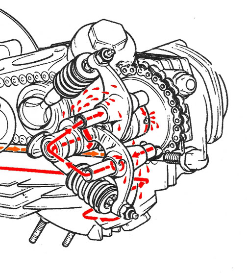
As you can see in the drawing below from the Honda Shop Manual, the oil is pumped up the 5 o’clock cylinder head stud (the one with the acorn nut and washer on it) into the hollow exhaust rocker arm, then exits the hollow exhaust rocker arm shaft and continues to lubricate the cam and the intake rocker arm shaft before returning to the crankcase. Since the only way the top end oil can “escape” is thru the small holes in the cam and rocker arm shafts, the system is always under pressure, which is a very simple and effective design. What is not shown is the exhaust rocker arm side cover. This cover distributes the oil from the exhaust rocker arm shaft to the cam and intake rocker arm shaft.
Here’s a close up look at the oil flow in the CT90 head area.
Design:
Based on my research, I decided the best option for stressed out, over heated, oil would be a radical oil bypass proceedure – intercept the oil leaving the exhaust rocker arm shaft, run it thru the oil cooler, then return the cooled oil to lubricate the cam and intake rocker arm systems. Fortunately the valve rocker arm side cover is thick enough to safely drill and tap.
I have a spare head that I rebuilt and “pocket ported” for a big bore project on a CT. I figured I had little to lose if the oil cooler customization didn’t work out. The worse that could happen is that the existing top end would be destroyed from lack of oil.
Potential Benefits:
As oil moves throught an engine it “absorbs” heat from friction and the combustion process. By cooling the oil you are actually helping to cool the engine. The cooler the oil, the more heat can be extracted from the engine. An oil cooler has much the same function as a radiator in a water cooled engine. Both are taking a heated liquid, cooling it down and returning it in a continous heat/cool cycle. Circulating another 1/2 quart of oil that is in the oil cooler can’t hurt either.
Since I was going this far, why not also add a Crankcase Breather and filter? The 4mm larger piston of the big bore project will contribute more back pressure, so having a crankcase breather that would relive the pressure seemed like a good idea.
I like to keep riding, so I went on Ebay and got a couple of valve rocker arm side covers in good condition. I dislike it when I mess up and can’t ride while waiting for replacement parts.
Oil Cooler and Plumbing Parts List:
I have used Earl’s Performance Plumbing coolers in many diverse applications over the years.
Earl’s are much more efficient than the “tube & fin” type of oil cooler. If you look at the design, you will see that they are much like modern aluminium “cross flow” radiators now common in cars. Earl’s “Narrow” model just happened to fit, so why not go with a proven design?
You can use the Search function and the part numbers shown below on the Earl’s web site to find each part.
- One – Earl’s, Gray – “Narrow”, 7 row, oil cooler, Earl’s # 20706ERL.
- Two – AN6 to 1/4″ NPT adapters, Earl’s #981606ERL, for the valve rocker arm side cover bypass hose end fittings.
- Two – AN6, 90 degree Super Stock hose ends, Earl’s #709167ERL, to point the hoses UP, out of harms way from the valve rocker arm side cover to the oil cooler. (I didn’t want anything to grab the oil cooler hoses).
- Four Feet – AN6 Super Stock blue hose, Earl’s #790006ERL, more than enough, with a little extra, “just in case”.
- Two – Oil cooler AN6 adapters, Earl’s #585106ERL, to reduce AN10 to the AN6 hose end fittings. The oil cooler should come with these, mine did.
- Two – AN6, 150 degree Super Stock hose ends, Earl’s #715067ERL, to point the hoses DOWN from the oil cooler to the valve rocker arm side cover adapters.
- One – Aluminium mounting bracket set, Earl’s #1707ERL, to safely and conveniently mount the oil cooler.
- Four – 3/4″ cushioned tubing clamps, Earl’s #171012ERL, to mount the oil cooler to the CT90 Skid Plate supports. This package contains 5 clamps, 4 to use, and 1 to lose.
- One – CT90 valve rocker side cover gasket.
While at the Earl’s store gathering up the parts, I picked up a copy of their Performance Plumbing Catalog. It is full of usefull perormance plumbing information, especially the “Assembly Instructions” in the Technical Section.
Procedure:
The valve rocker arm side cover attaching screws, usually require using your impact screwdriver to convince them to be loosened and removed.
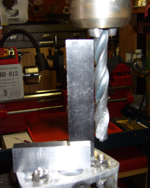
The valve rocker arm side cover was squared in the drill press as I didn’t want any crooked holes.
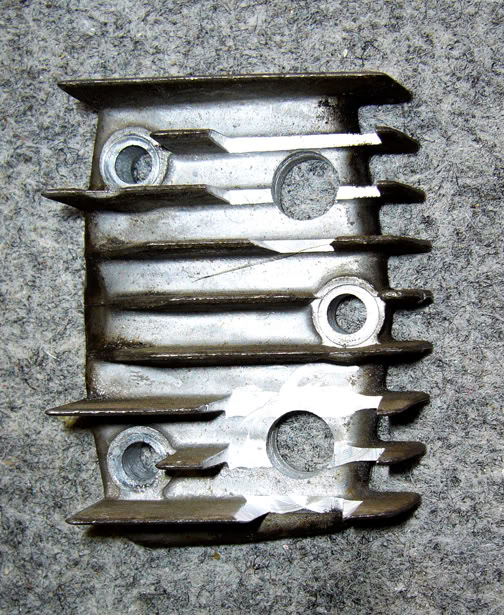
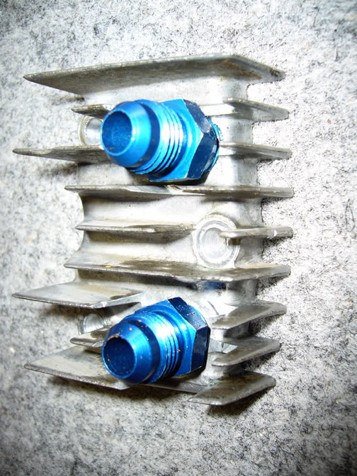
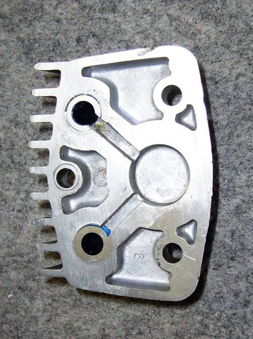
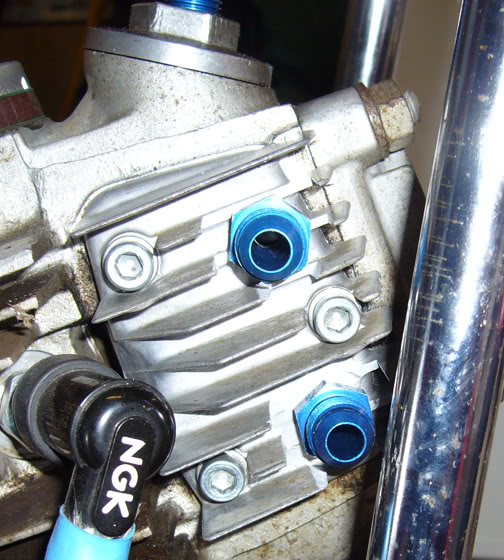
Using the valve rocker arm side cover gasket as a guide, two 7/16″ holes were drilled to align with the hollow rocker arm shafts.
An end mill tool bit was used to “counter bore” the fins, so that a 5/8″ socket could be used to torque the AN6 hose fittings.
A 1/4″ NPT tap was used to tap the threads for the AN6 to 1/4″ NPT adapters. The adapters and tapped holes were throughly cleaned, then liberally coated with Locktite 603 Retaining Compound and really torqued in place. They must not move when attaching or removing the hoses. I scribed a small mark, so I can detect any movement in the future.
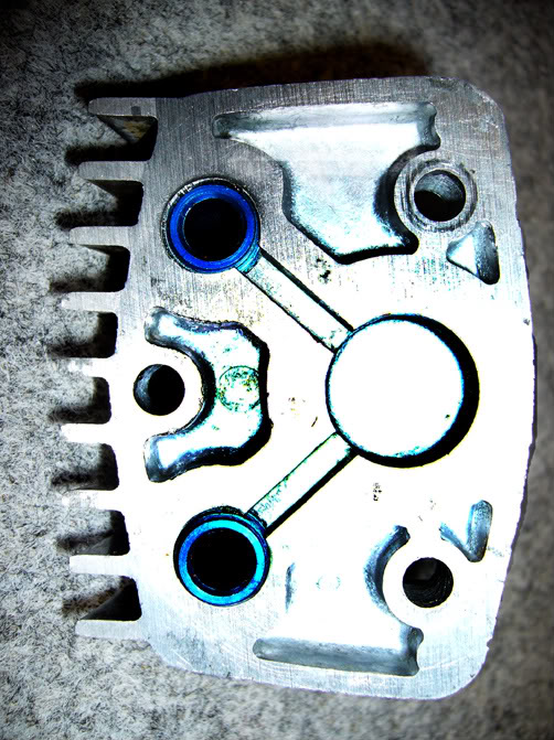
I considered filling the slot that runs from the exhaust rocker arm shaft (the bottom one) to the cam and intake rocker arm shaft with JB Weld. Pressure testing showed that this was not necessary since the gasket will seal and not permit any bypass oil to leak into its “original path”.
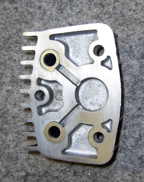
The fittings were milled flush on the inside.
Flush fittings.
And, the intake rocker arm shaft fitting (the top one) was slotted to allow oil to flow to both the rocker arm shaft and down to the cam.
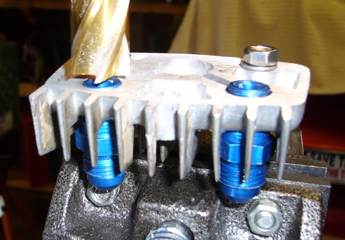
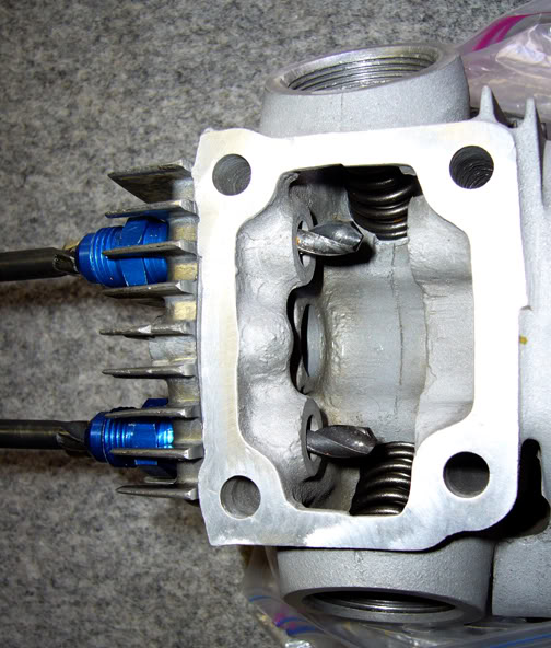
The alignment was checked on a spare head by inserting drill bits thru the fittings. The drills went all the way into both rocker arm shaft journals. Everything lined up, so far, so good.
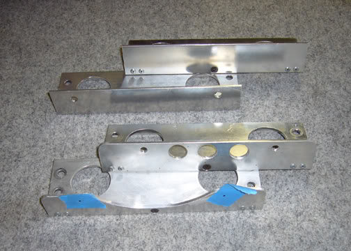
The oil cooler mounting brackets were modified for maximum air flow to the head and cylinder (bottom of the photo below).
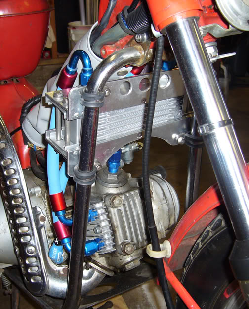
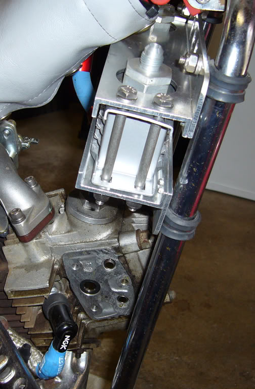
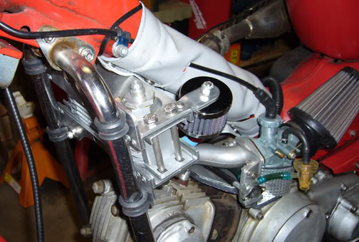
The brackets were attached to the oil cooler and the oil cooler attached to the skid plate supports.
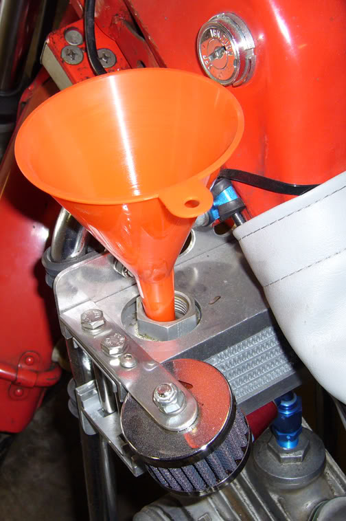
Important Note: The oil cooler was mounted with the fittings on top, as recommended by Earl’s. This prevents the oil from draining back in the engine, causing the oil level to rise to a possibly dangerous level (we’re talking about 50% more oil). Worse, the cam and intake rocker arm shafts would run dry until the hoses AND the oil cooler filled with enough oil to begin lubrication – NOT GOOD!
Note: the Crankcase Breather customization that you can see in the above and below photos is described on another web page, click the above link.
The oil cooler was manually filled with oil.
The valve rocker arm side cover was installed with a new gasket using a dab of anti-seize on the new allen head stainless stell screws.
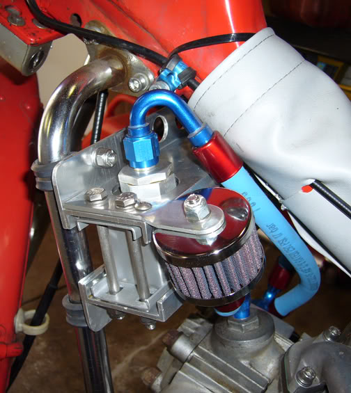
The hoses were cut to fit and pushed on the hose end fittings. The hose assemblies were attached to the oil cooler and valve rocker arm side cover completing the project.
After several trial routing of the hoses, I chose to route the bottom fitting on the valve rocker arm side cover, across to the left (inlet) fitting on the oil cooler and the top fitting straight up to the right (outlet) fitting.
Note: the Crankcase Breather customization that you can see in the above photo is described on another web page, click the link.
What, you say… I’m not using stainless braided hoses? Past plumbing mishaps taught me to always prototype with rubber hoses. They are much cheaper and easier to work with. And, OK, yes, true to form, I did cut one hose just a wee bit too short.
The “Super Stock” rubber hoses are rated at 250 psi and 250 degrees F, more than adequate for a CT90. Not only that, they are tucked in, and out of harms way, so they should be just fine as is. Overkill or not, sooner or later I will probably remove the rubber hoses and take them to the Earl’s store near me to have them make a set of stainless braided hoses, or just make them myself, they do look way cool!
A final check just to make sure all the fittings and fasteners are tight and we’re ready to go.
Results:
Oil cooler leak test – Engine running, no oil leaks! After the initial test the oil level was checked and topped off, to crankcase specifications.
Oil cooler throughput test – The oil cooler outlet hose fitting on the valve rocker arm side cover (the top one) was loosened with the engine running and as planned, oil squirted out. Oops, didn’t plan that it would squirt all over me, however. Passed this test, as oil is being pumped thru the oil cooler. I re-tightened, cleaned up the mess, changed my shirt, then re-checked once more, no leaks.
Oil cooler performance – As the engine was warming up, placing a finger on the inlet oil cooler fitting indicated that he oil was getting warm, while the outlet fitting remained cool to the touch. The oil cooler was doing its job. A test ride confirmed that the inlet side started getting hot, to the point where I couldn’t leave my finger on it very long, while the outlet side remained much cooler. My laser temp gauge read the inlet fitting at 190 degrees F, while the outlet fitting was 127 degrees F. I let the engine idle for several minutes insuring no airflow across the oil cooler. Even without air flow the inlet temp was 203 degrees F, and the outlet temp was 157 degrees F. Very impressive.
Oil Changes
Normal (drain from engine) oil changes can be done, knowing that about 1/3 of the dirty oil is still inside the oil cooler. To compensate, I change the oil more often, basically when it starts looking dirty, so I don’t consider this a problem.
Every 3-4 oil changes, I disconnect one of the hose end fittings from the oil cooler. Earl’s oil coolers have large AN10 fittings going into the oil cooler. By removing one of the hoses you can easily suck out the old oil, then refill the oil cooler with fresh oil and you’re good to go.
Final Thoughts
After a couple of days of riding, I disassembled everything and found oil in all the right places, with no sign of oil starvation – success!
I’ll also be exploring if this customization will work for a CT110, which may have a slightly different oil flow path in the head. On a CT110, the 5 o’clock AND the 10 o’clock, cylinder head studs, both carry oil to the head, unlike the CT90 which has only the 5 o’clock cylinder head stud carrying oil to the head. Once I get my hands on a CT110 head, I’ll know more.


Leave a Reply