This is a continuation of my previous post http://www.l8ter.com/?p=390 . This post will basically focus on the building of the dolly and getting it ready for the miniE controller.
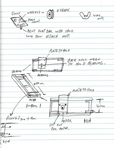
So here was my initial brain storm;
After thinking about it for a while longer it looked more like;
I didn’t see any need to design it fully rather I went and built it off the cuff.
I grabbed;
 2m of Aluminum C channel, I was wanting 40x40mm at 3mm thick but unfortunately they didn’t have any so i settled with 25mm * 40mm @ 3mm thick. I think if i were to do it again i would try and get 50mm high in the center, 25mm is fin for the top and bottom however. The C channel is for the runners either side, it should be cut into 2 x 1m lengths (Or longer if your going longer)
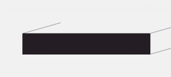 1.5m of Aluminum flat bar 50mm width by 3mm thick. the 50mm flat bar is used for braces to keep the C channel from moving.
1m of Aluminum flat bar 25mm wide by 3mm thick (any where from 15mm onward will work.). This is used in several places e.g to hold the dolly platform to the nut on the screw drive, to securing the bearing.
3mm aluminum plate 160mm*140mm this is for the platform, this will be what you attach the tripod head will mount to.
I got all the above metal for about $56
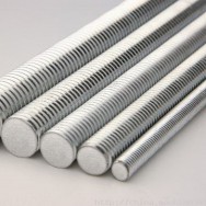 1m 3/16″ (Or whatever size you want to use) threaded rod to work as the screw drive system (Bunnings has this)
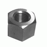 1x bolt for the above threaded rod
Additional Hardware;
Optional: Drill press (But it makes life a hell of a lot easier)
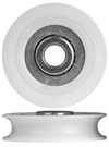 4x Roller wheels (used in kitchen drawers, sliding doors etc, These ones are rolltrak wheels 4060, easy to get a Bunnings hardware stores but they are a tad hexy at $9 each.
Pack of 10 short (~10mm) 1/4″ bolts and nuts
Pack of 10 long (~30mm) 1/4″ bolts and nuts
Pack of 30 1/4″ flat washers
Pack of 10 1/4″ wing nuts (to help with tightening or loosening parts in the field.
Pack of 100 rivets 1/8″ width and 3/6″ grip (enough grip to do 6mm – 9 mm thickness)
Drill bit to suit rivets
Pack of small cable ties
Optional: 4 rubber feet
Hose clamps (smallest)
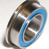 Bearing 3/16″ flanged (lawn mower shop, skateboard shop etc), friend Chucky hooked me up with this one, a tad expensive at 20 odd dollars but great quality, and local pickup).
 2x Parallel (Or in my case I used DB9 Serial port as i only needed 9 cables as i didnt want to use the focus line and i already had the parts)
So lets start some light walk through of what I did (If you need more detail just leave a comment and i will get back to you)
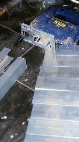
Using a jigsaw and an aluminium blade I cut the 2m C Chanel in half, I then cut the 1.5m of 55mm flatbar into 8 sections of 180mm. One one piece of that 180mm into 2 pieces of 90mm.
Using the stepper motor (Same one from part 1 of this tutorial), I cut out a section of one of the 180mm 55mm flat bars to help the motor sit flush (This is only needed with the 40mm height C channel, So the motor sits flush).
THE BEARING END OF THE DOLLY:
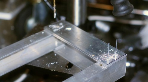
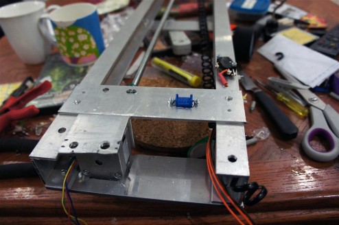
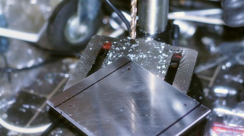
I clamped together one of the 55mm flat bar and the parts of C channel , and drilled 4 holes at 25mm from each edge FOR THE TOP SIDE, BEARING END. Each time I would get one hole drilled I would insert the rivets to help stop the dolly moving. On the UNDER SIDE OF THE BEARING END I put 2x 180mm pieces of the flat bar to give a mounting point for 2x tripods in future (one each end).
NOTE: when one side is complete measure the gap EXACTY, then ensure when drilling the other end that the gap remains constant (+/- 1mm), Otherwise the platform may have un wanted movement when sliding down the frame. Once those both ends are done then drill the center underside mount, again ensuring the gap doesnt change.
THE MOTOR END OF THE DOLLY:
Pardon the recent image, i didn’t take an early image of this part) Again the underside is made of 2x 180mm *55mm flat bar (1x piece with the motor cut out if required as per instructions a few images above), Again for the underside I drilled 4 times, once in each corner 25mm from each side. The top however for this end will be removable to help fix and replace parts in the field, So it is drilled on opposite corners using a 1/4″ drill bit and secured using one of the 1/4″ short nuts and wing nuts. I also drilled and cut out a hole for my DB9 connection or in most peoples cases the parallel port, then secured using some small screws and nuts i had lying around the shed.
THE PLATFORM THAT TRAVELS ON THE DOLLY RAILS:
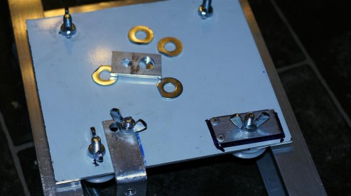
This bit is a bit fiddly and this is where you could do a little bit of maths to work out where the wheels should go to fit snuggle between the rails. I didn’t go the maths route as such but this is how i did it: I put one wheel on it approximately where i thought it should go, marked that spot, then using a set square I marked where the second wheel should go (on the same side) and drilled the first 2 1/4″ holes for the wheels, i then mounted using two of the longer 1/4″ bolts and wind nuts. I then sat the two wheels on one track (lets say for example the left track) then upside down i put the 3rd and 4th wheel on, and marked their position. I then drilled about 1-2mm closer to the edge than my markings to ensure a tight fit eliminating any vertical movement. (I actually had an issue where somehow my square of aluminum wasnt square so my 2nd initial wheel wasnt in the right place (so the dolly was loose). I fixed it by expanding the hole drilled on the aluminum platform so the wheel can be where it needs to be, then cutting a piece of the smaller flat bar (about 40mm long) and drilling a 1/4″ hole then moving the wheel to where it needed to be. Then drilling 2 holes for rivets to hold the fix in place. (This is why people use plans :P)
MOUNTING THE MOTOR TO THE END OF THE DOLLY:
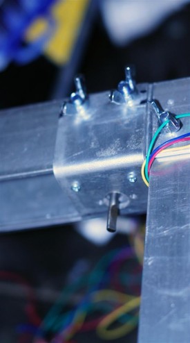
This bit is fairly confusing and difficult to explain. This stepper motor mount sits on top of the end piece of the dolly like…
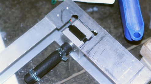
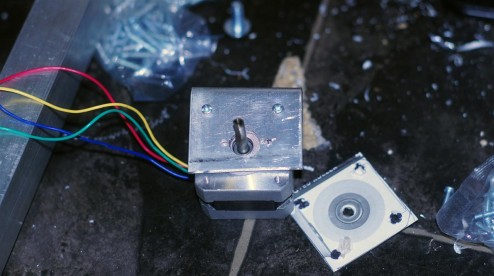
I bent one of the 90mm long 55mm wide flatbar in a little less then half (55mm * 35mm) just by putting it in a vice and hammering it into a right angle. Using a piece of scrap cardboard i built a rough template for the stepper motor. I put the motor into the dolly and screwed the top down, then I marked where the center of the motor is using a pen. I then trilled a 1/4″ hole into the center of this marking (the shorter side), The hole is bigger so we can move the motor to the spot needed.. I also drilled 2 1/4″ holes in the top half (the longer bit), and the top of the dolly. I then bolted it together and used the cardboard template i marked the two screw holes that needed to be drilled out for the motor to mount to, then using some screws i mounted the motor on.
CONNECTING THE MOTOR TO THE SCREW/THREADED ROD:
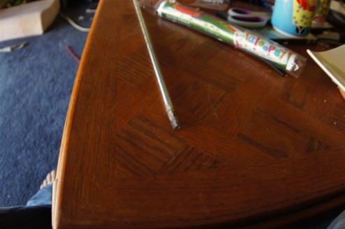
With the threaded rod I ground flat about 2cm of the rod, This is to help the hose and clamps to grab.
(yes i did show this picture before, but this is for a different reason) I also ground down the motor drive pin so it had a flat spot on it, again to help the clamps lock on to the pin.
The above video explains how to get the coupling to the drive shaft of the motor to work with the threaded rod and sit center. (0:45 is the golden details)
CONNECTING THE BEARING TO THE THREADED ROD:
On a flat surface measure the height of the threaded rod at the motor end, also measure the offset from the edge of the dolly to the threaded rod on the motor end, it needs to be within a 1-2mm tolerance. Just like the motor mount this will sit on the other end of the dolly and keep the threaded rod level and true. Using the previous measurements mark a point on the bearing mount to drill a hole for the bearing to fit in. As the bearing hole is huge i didn’t have a drill big enough, so i ended up cutting 5 smaller holes then using a rounded file, filed it to the correct size. (This is pretty easy as aluminum is soft but still took 20 odd minutes).
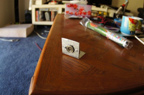
To hold the bearing in place on the flange side I used a 55mm long piece of the smaller flat rod with a hole a bit bigger then 1/4″, I then drilled two more holes. One i riveted, the other one i screwed down. I screwed one side down so if i need to replace the part in future i can do that without drilling out rivets. This will be mounted to the dolly with a 1/4 bolt (offset so it doesn’t interfere with the threaded rod), But i would suggest taping it down temporarily until the location of the mount is confirmed.
CONNECTING THE PLATFORM TO THE THREADED ROD
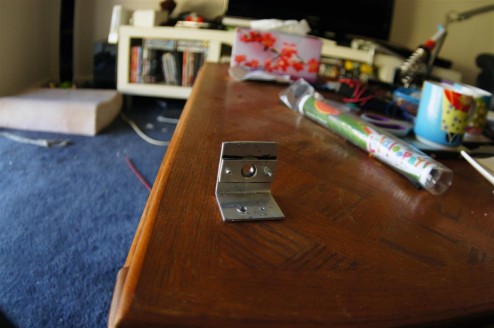
Using a 90mm length of the smaller flat bar make a bend of 90 degrees (~45*45 should do it, longer on top). Using the measurements above mark the spot that the threaded rod will pass through. Drill a hole bigger then the threaded rod at this mark. Temporarily slide this folded piece onto the threaded rod, put the nut on the threaded rod in front of the folded piece you just added (A hand drill is handy here to spin the threaded rod quickly to help you move the nut on and off quickly). place a washer vertically on top of the nut on a flat spot, mark this point. (Your doing this so that the nut cant spin when the threaded rod is sun). Cut a a 45mm piece of the smaller flat bar, Drill the same size hole you did previously for the threaded rod to fit through. Take the folded piece and the nut off. Drill a 1/4″ hole on both the newly cut piece and the folded piece,. THis will allow you to put a polt through these pieces with washer in between so that the nut cant spin, I had to grind a flatspot on the washers to help it not to move (also because my hole was slightly too low).
Now i realize that is another section thats hard to follow, but here is is hard to follow but here is a video explaining:
Don’t drill this part into the platform yet.
FINISH BOLTING PLATFORM AND BEARING:
As per this video just tape the bearing mount and the platform mount, make a marking showing you where the mounts are sitting so you can ensure there is no movement. Now run the dolly backwards and forwards using just the motor shield and the code provided in the bildr tutorial, just modify it to keep running in a direction forever, and disconnect the easydriver power to stop it,. JUST WATCH IT SO IT DOESNT HIT THE END OR IT CAN RIP APART THE DOLLY. Do both directions ensuring there is no binding of the mounts etc. Once I was sure its ok i drilled a 1/4″ hole on both mounts ensuring it clears the threaded rod. I used only one bolt on each because the threaded rod may be slightly bent and this gives the mounts enough horizontal movement to keep it in check.
GETTING THE DOLLY READY FOR THE ARDUINO:
So now you have an almost complete dolly, now we just need to add a few small items;
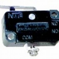 2x Limit switches, this will be what tells MiniE to stop moving the motor. (These are SPST microswitch SM1040 at Jaycar)
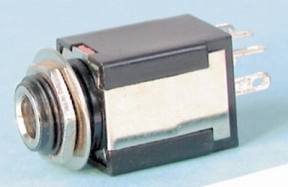 1x Stereo jack (I’m using mono as I don’t want/need focus but this will let you do shot and focus)
Optional: Terminal for wires.
Some electrical wire, old coiled telephone cable
INSTALLING THE LIMIT SWITCHES
<images of switches to be included later>
At each end of the dolly I drilled and mounted the switches, both switches share a common 5V wire, and each switch also has its own individual return wire. As i could only get the 25mm width C channel i had to mount my switches on an angle which mean I had to bend the contact so the dolly would stop before hitting the body of the switch.
<image of cable ties to be included later <>
I drilled holes along the side to allow me to cable tie the cables out of the way so they don’t interfere with the platform moving. I labeled allt he cables so i know which one is which, again this will make it a hell of a lot easier if in the field it stops working.
<Image of terminal to be included later <>
I also included a terminal at the motor end, again to make life easy if you need to fix something.
INSTALLING THE CAMERA TRIGGER
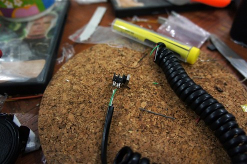
This is the mono version as i didn’t want the focus part of the MiniE, but the stereo plug is exactly the same. I’m actually using a coiled telephone cable here as it has the property of pulling itself back to stop it getting caught on things. I drilled a hole in the platform and screwed this in. I also drilled some holes for cable ties and cable tied about 3cm on the dolly, this should stop any chance of the cable being ripped off the dolly in case it gets stuck. The camera trigger connects to this directly on the platform. The other end of this goes to the last cable tie on the motor end of the dolly, again to stop the cable being ripped out in case it gets caught.
CABLING IT TO THE SERIAL PORT:
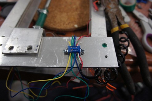
Now this bit is easier if you have some ribbon cable, I didnt so i did it by hand, i made sure I drew up a diagram for myself.
Just grab your multi-meter in circuit check mode and check none of the pins (excluding the stepper motor pins) form a circuit. If they do try again, something is connecting where it shouldn’t. Also double check that all the pins go to where they are meant to, you don’t want to accidentally send 5V down to your shiny camera do you?
Anyway at this point the system works, here is the test shot i did:
You may also be wondering why I chose the threaded rod instead of a motor with rubber tires, it was because i wanted enough lift for heavy camera gear at angles: here was the stress test i did of the dolly lifting abotu 3kg:
This is the end of Part 2, Part 3 should be up within a few days as there isn’t much to that section.
Let me know any questions, comments etc Happy to help.

6 Nov ’11 at 11:45 pm
This looks really really cool. I actually worked on a project just like this last week. It plugs into dragonframe 3.0 so it is controlled by the software too. Pretty nice software.
17 Nov ’12 at 6:51 am
Afternoon, Great article. Trying to do the same. Did you only use the stpper you mention? https://www.sparkfun.com/products/9238
It was able to hold the weight on the duffle. I was lead to believe i had to buy something bigger. I ended up going with this: http://www.phidgets.com/products.php?product_id=3307_0
Would love to ask more questions 🙂
17 Nov ’12 at 6:26 pm
Yeah i just used that stepper, didnt really need anything bigger as using a threaded rod gives you small increments of movement with little to no effort. The biggest single point of failure with this setup is the host couple, but its a small risk. I’m actually throwing around a new crazy design for motorized tripod wheels. As while this is great its really difficult to take with you anywhere via plane etc (without people thinking its a bomb). Throw me an email if you want to talk further eraser (at) l8ter . com or find me on twitter ozeraser.