Adafruit.com had a design an electric Halloween graphic contest. I wanted to make something cool and unique. I then came to the crazy idea of making a logo that could actually be etched onto a PCB board and be used.
I first had to decide on a schematic, remembering my childhood I remember making a simple transistor based flashing unit. After some searching I found the exact schematic I was thinking about:

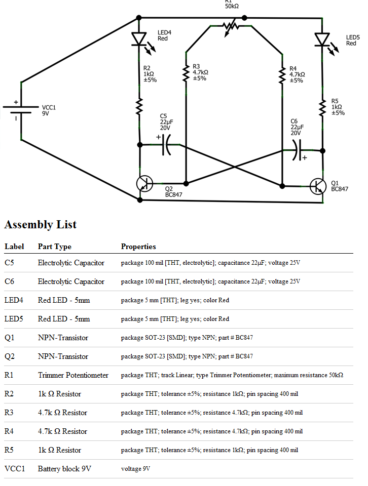
This was almost exactly what i had in mind, but I thought I could integrate a Trimpot into the mix, to not only make the item more fun but to give it a little bit more complexity. So here is the schematic & part list i ended up using:
This circuit will run fine with anything from 9 – 12 volt. Here is the prototype breadboard setup of the above circuit:
From here I designed the Halloween graphic using the lines as the circuit, and ended up with:
TO ETCH I PRINTED AT 10cm HIGH BY 7.27cm WIDE
FOR SIMPLE CORRECT SIZE ETCHING PRINT THIS BMP FROM PAINT, (in page setup unselect scaling, and select 100% of normal size)
The large squares are the pads for the items to be soldered onto, they are a tad larger then normal to make soldering easy and quick for beginners. Something else to note is it doesn’t have through holes so you surface mount the components to the board (will show this in more detail later on. I followed this tutorial on how to easily etch a PCB using a laser printer and overhead transparencies:
Picture of the cut Single Sided PCB and the design printed onto overhead transparencies (I noticed the fresher the print the better it transfers to the copper)
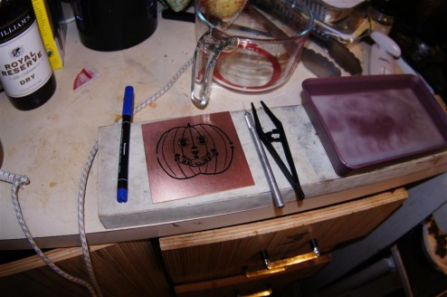
Picture of the design after it was transferred to the copper PCB and touched up using a marker pen.
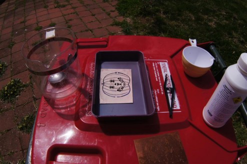
Picture of the PCB being etched (I wasnt able to put my hands on any Ferric Chloride)
Picture of the PCB after being etched, from here using an medium abrasive pad you scratch the toner off to reveal any tracks.

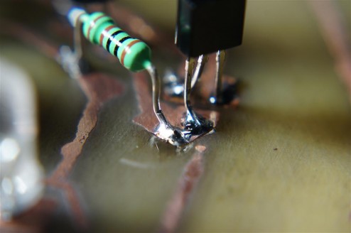
I had a few issues here where the toner had slightly smudged and made some lines touch, so using an exacto knife I cut those copper sections out, then tested the whole board with a multimeter to ensure there were no other crossed tracks. Now onto soldering the parts onto the board. As I didnt want to do holes for the components I decided I would just surface mount components (Which is even a standard {Thx Simon}). To surface mount the components you just bend them (With needle node pliers) so they have feet e.g:
Once soldered onto the board (Using a peg, 3rd hand, aligator clips to hold it in place) they look like:
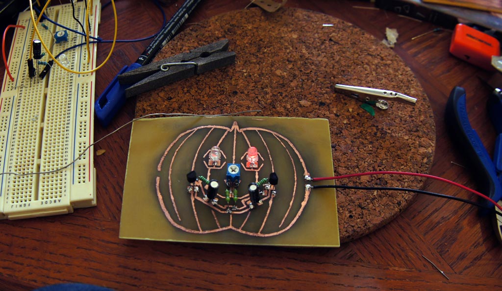
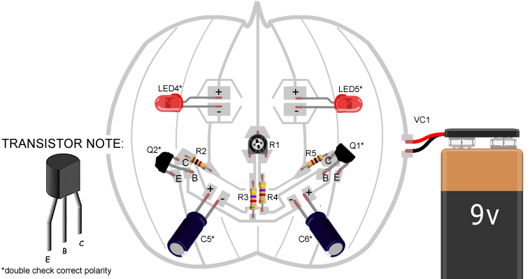
 So now youre ready to solder where do all the bits go (looking at the previous schematic for corresponding labels?:
Once you have soldered the board together and double checked all polarities, and connect it to 9v-12v and watch it work:
So there you go, a transistor flasher. I had lots of fun thinking, designing and making it. Let me know what you think, and if you hack or change it in any way. And fingers crossed that Adafruit like it enough to use it.
Also I should thank Joanne my other half who had to put up with me working into the wee hours of the morning, Simon from work who helped me understand and find issues with the pcb design. Jake for helping me source some transparencies and anyone else I have bugged through-out the last week with this project.



Leave a Reply