This is a quick hack and slash to capture what i did and used to get this printrboard motor controllers working with the Arduino IDE

Things you need to get started, Printrboard, USBTinyISP (or use an arduino to program (http://www.instructables.com/id/Turn-Your-Arduino-Into-an-ISP/), one motor to test i guess.
Download and install winavr (https://sourceforge.net/projects/winavr/?source=typ_redirect) I used 20100110.
Download and install Arduino I successfully use version 1.6.8 (arduino.cc)
Download Arduino HID support pack ( https://github.com/scwimbush/Printrboard-HID-Arduino-IDE-Support) extract to hardware folder in arduino (cached copy Printrboard-HID-Arduino-IDE-Support-master )
Download Stepper driver library (https://github.com/laurb9/StepperDriver) extract to the libraries folder in the Arduino folder. Chached copy here StepperDriver-master
Hookup your USBtinyISP to your printrboard ISP 6pin header *RED line on ribbon cable towards the sd card slot*
Dont hook any power to the printrboard (no usb no 12V)
Plug USBtinyISP to the pc, wait for driver to install if you cant find (x64 etc) it here it is usbtiny_signed_8
Open command prompt, navigate to the arduino hardware directory as follows (C:\Program Files (x86)\Arduino\hardware\printrboard\avr\bootloaders)
run “avrdude -c usbtiny -p at90usb1286 -U lfuse:w:0xde:m -U hfuse:w:0xdb:m -U efuse:w:0xf0:m” Wait for completion
run “avrdude -c usbtiny -p at90usb1286 -U flash:w:BootloaderHID.hex:i – See more at: http://blog.lincomatic.com/?p=548#sthash.rAaaAdym.dpuf” It may error at the end but this should work.

Unplug USBTinyISP, Plug printrboard to the pc, ensure boot jumper is on the board, plug in 12v to board. Turn it on it shouldnt require any drivers. plug a stepper motor into the Z-Motor header.

Open Ardunio, Load up the Examples -> Stepper Driver -> Basic Stepper Driver sketch (if you dont have it you didnt install the library correctly earlier)
The following modifications are using only Z motor however here is the entire list of pins that the marlin system (https://github.com/lincomatic/Marlin/blob/Marlin_v1/Marlin/pins.h) uses;
/****************************************************************************************
* Printrboard Rev. B pin assingments (ATMEGA90USB1286)
* Requires the Teensyduino software with Teensy2.0++ selected in arduino IDE!
* See http://reprap.org/wiki/Printrboard for more info
****************************************************************************************/
#if MOTHERBOARD == 81
#define MOTHERBOARD 81
#define KNOWN_BOARD 1

#define X_STEP_PIN         28
#define X_DIR_PIN          29
#define X_ENABLE_PIN       19
#define X_MIN_PIN          47
#define X_MAX_PIN          -1

#define Y_STEP_PIN         30
#define Y_DIR_PIN          31
#define Y_ENABLE_PIN       18
#define Y_MIN_PIN           20
#define Y_MAX_PIN          -1

#define Z_STEP_PIN         32
#define Z_DIR_PIN          33
#define Z_ENABLE_PIN       17
#define Z_MIN_PIN          36
#define Z_MAX_PIN          -1

#define E0_STEP_PIN         34
#define E0_DIR_PIN          35
#define E0_ENABLE_PIN       13

#define HEATER_0_PIN       15  // Extruder
#define HEATER_1_PIN       -1
#define HEATER_2_PIN       -1
#define HEATER_BED_PIN     14  // Bed
#define FAN_PIN            16  // Fan

#define TEMP_0_PIN          1  // Extruder - ANALOG PIN NUMBERING
#define TEMP_1_PIN         -1
#define TEMP_2_PIN         -1
#define TEMP_BED_PIN        0  // Bed - ANALOG PIN NUMBERING

#define SDPOWER            -1
#define SDSS                26
#define LED_PIN            -1
#define PS_ON_PIN          -1
#define KILL_PIN           -1

#ifndef SDSUPPORT
// these pins are defined in the SD library if building with SD support
  #define SCK_PIN          21
  #define MISO_PIN         22
  #define MOSI_PIN         23
#endif

#ifdef ULTRA_LCD

  #ifdef NEWPANEL
  //arduino pin which triggers an piezzo beeper
    #define BEEPER 33			// Beeper on AUX-4

#ifndef MCP28017_LCD
    #define LCD_PINS_RS 16
    #define LCD_PINS_ENABLE 17
    #define LCD_PINS_D4 23
    #define LCD_PINS_D5 25
    #define LCD_PINS_D6 27
    #define LCD_PINS_D7 29
#endif // MCP28017_LCD

    //buttons are directly attached using AUX-2
    #define BTN_EN1 11 // PC1
    #define BTN_EN2 12 // PC2
#ifndef PANUCATT_VIKI
    #define BTN_ENC 31  //the click
#endif

    #define BLEN_C 2
    #define BLEN_B 1
    #define BLEN_A 0

    #define SDCARDDETECT -1		// Ramps does not use this port

      //encoder rotation values
    #define encrot0 0
    #define encrot1 2
    #define encrot2 3
    #define encrot3 1

  #else //old style panel with shift register
    //arduino pin witch triggers an piezzo beeper
    #define BEEPER 33		No Beeper added

    //buttons are attached to a shift register
	// Not wired this yet
    //#define SHIFT_CLK 38
    //#define SHIFT_LD 42
    //#define SHIFT_OUT 40
    //#define SHIFT_EN 17

    #define LCD_PINS_RS 16
    #define LCD_PINS_ENABLE 17
    #define LCD_PINS_D4 23
    #define LCD_PINS_D5 25
    #define LCD_PINS_D6 27
    #define LCD_PINS_D7 29

    //encoder rotation values
    #define encrot0 0
    #define encrot1 2
    #define encrot2 3
    #define encrot3 1


    //bits in the shift register that carry the buttons for:
    // left up center down right red
    #define BL_LE 7
    #define BL_UP 6
    #define BL_MI 5
    #define BL_DW 4
    #define BL_RI 3
    #define BL_ST 2

    #define BLEN_B 1
    #define BLEN_A 0
  #endif
#endif //ULTRA_LCD

#endif
Set the following (16 steps because the drivers do 1/16);
// All the wires needed for full functionality
#define DIR 33
#define STEP 32

// Since microstepping is set externally, make sure this matches the selected mode
// 1=full step, 2=half step etc.
#define MICROSTEPS 16
And once you have done that we make a small modification to set that motor driver to enabled by going low on the enable pin.
void setup() {
    /*
     * Set target motor RPM.
     * These motors can do up to about 200rpm.
     * Too high will result in a high pitched whine and the motor does not move.
     */
      pinMode(17,OUTPUT); // Enable
       digitalWrite(17,LOW); // Set Enable low
    stepper.setRPM(120);
}
Now remove the boot pin on the printrboard, press the reset button, you should hear the usb connection sound in windows. Ensure the Arduino software is set to install via Printrboard board. Then click upload in the Arduino software, when it is complete it will reset the board. Power the board off replace the jumper and turn it back on. The motor should now be woorking.
This concludes this quick getting the printrboard working. Hopefully it is clear as mud, you should be able to figure it out from here 🙂
Here are a few links i used here:
https://github.com/scwimbush/Printrboard-HID-Arduino-IDE-Support
http://reprap.org/wiki/File:F4_Schematic.png
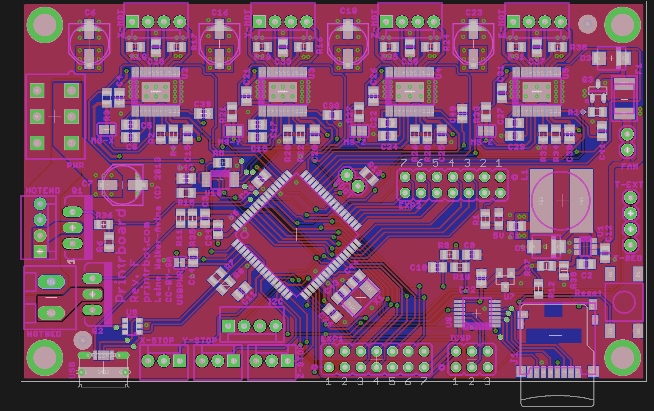
http://reprap.org/mediawiki/images/2/26/Printrboard_RevF_Board300.png
http://blog.lincomatic.com/?p=548
http://reprap.org/wiki/Printrboard
http://fritzing.org/projects/a4988-single-stepper-test/
https://github.com/laurb9/StepperDriver
https://github.com/lincomatic/Marlin/blob/Marlin_v1/Marlin/pins.h
http://reprap.org/wiki/Printrboard
https://bitbucket.org/makible/5dprint-firmware/wiki/EEPROM%20Settings
https://github.com/scwimbush/Printrboard-HID-Arduino-IDE-Support
http://printrbot.com/wp-content/uploads/2013/01/HelpFileForUsingPrintrboardElectronics-.pdf
http://blog.lincomatic.com/?p=502
6 Feb ’19 at 12:11 am
Thank you for writing down your notes on how to convert the printrboard back to an arduino. I have three broken printrboards that I was hoping to use for something since Printrbot didn’t want them back.
I have some notes for posterity sake. I’m not going to use the right terminology, but whatever.
I have the printrboard rev D. To load the program the board needs to be in bootloader mode, I think. Short the boot pins and hold the reset button. That will allow you to upload your compiled code.
The stepper will act strange if it’s working, because it’s running on the 5V line from your USB. You need to cycle the 12V power to the board and the stepper will start working the way you expect.
Also, microstepping on the A4988 is defined by what pins are pulled to ground (I think). From what I can tell the printrboard is hardwired to be 1/16, so the microsteps constant needs to be 16.
Here is the working program that runs one full rotation and delays 5 seconds: https://pastebin.com/pKBx047r
Thanks again!